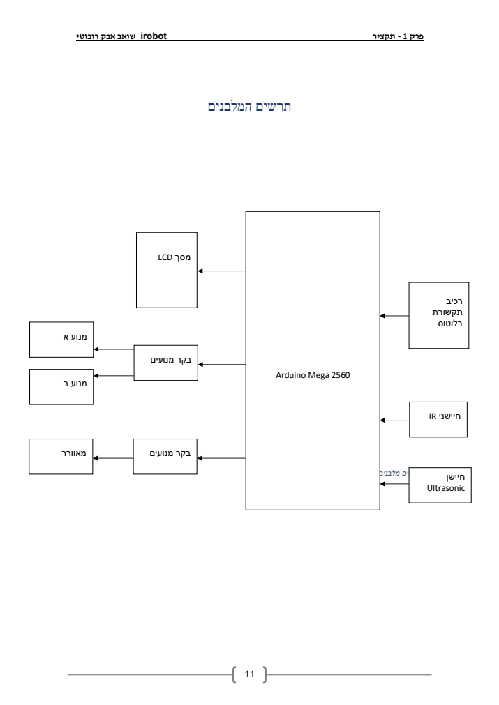
Arduino Mega 2560
The central controller coordinates sensors, motor outputs, the display, and Bluetooth commands.
Embedded systems · Team project
An Arduino Mega prototype combining autonomous obstacle avoidance, Bluetooth manual control, LCD feedback, and a motor-driven suction fan.
The goal was to build a floor-cleaning robot prototype that could move through a room, detect nearby obstacles, and choose a safe direction without continuous input from the user.
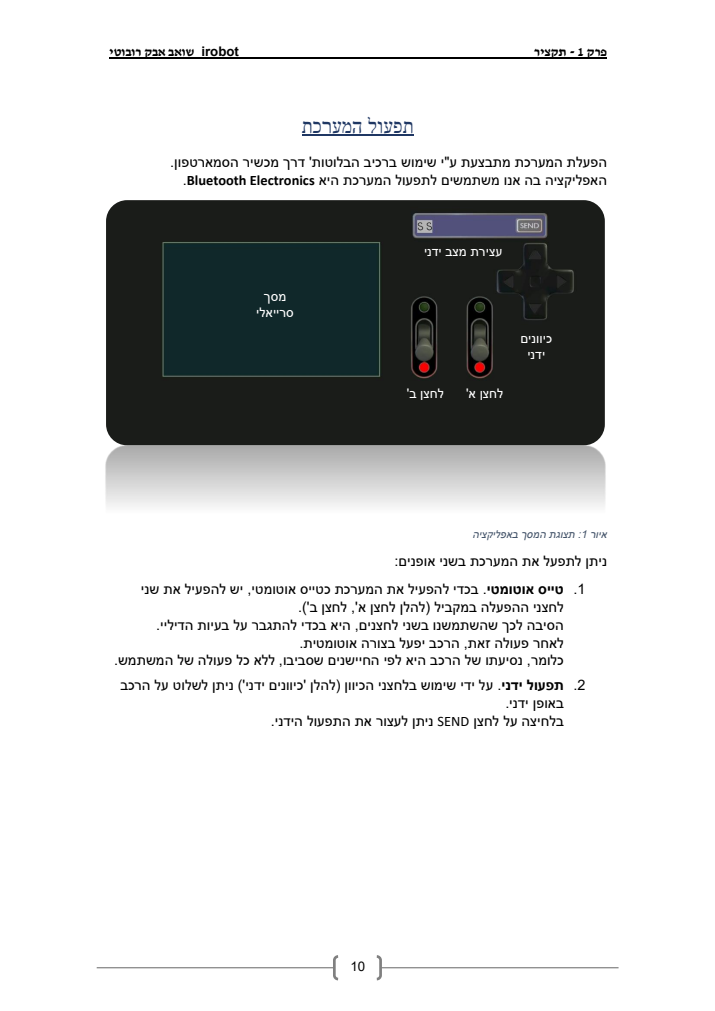
The same platform can switch to manual control through a phone. This made the project a complete embedded system rather than a single-function circuit: sensing, decision-making, actuation, and feedback all had to work together.
This was developed as a two-person team. I contributed across circuit design, wiring and soldering, component-level testing, embedded software, system integration, and technical documentation.
Working across the hardware and software boundary was the most valuable part: a sensor reading only matters when the control logic interprets it correctly and the drive electronics respond as expected.
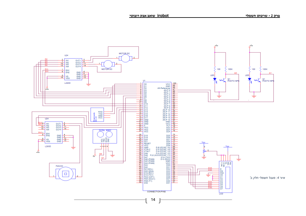
The Arduino Mega acts as the hub. It combines distance and edge information from three sensors, drives the motors and fan, listens for serial Bluetooth commands, and updates the LCD.
The central controller coordinates sensors, motor outputs, the display, and Bluetooth commands.
Two TCRT5000 infrared sensors cover the sides while an HC-SR04 ultrasonic sensor measures distance ahead.
L293D motor drivers control the two drive motors and the separate fan used to simulate suction.
An HC-06 module receives commands from a phone, while a 16×2 LCD reports movement and system status.
The software separates automatic navigation from direct manual commands. That keeps the behavior understandable and makes each motion routine reusable.
The project began with the circuit in OrCAD Capture, followed by wiring, soldering, individual component checks, and incremental integration with the Arduino code. Faulty components had to be identified and replaced during the build.
We built and programmed a working prototype with autonomous and manual control logic. COVID-era lab restrictions limited some final measurements, repairs, and full-system validation, so the result is documented as a prototype rather than a finished product.